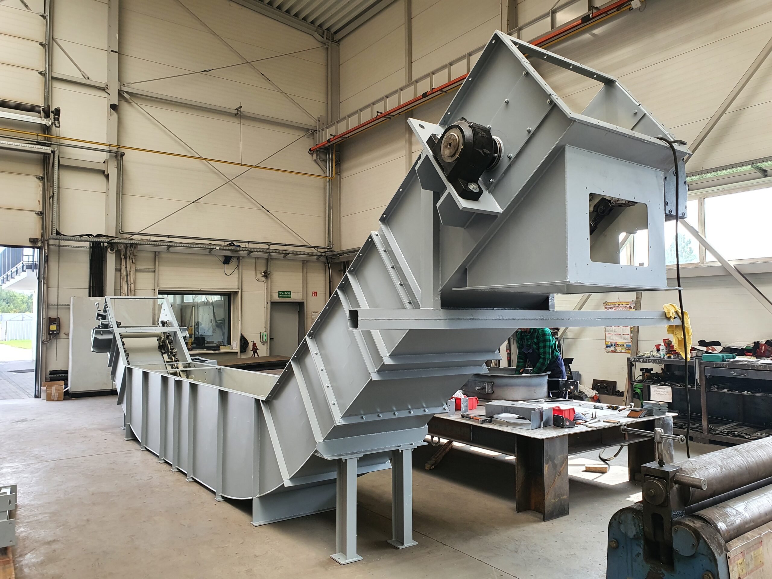
The modern chain conveyor is a piece of equipment with several key functions for recovering and transporting slag, which is made possible, among others, by its quenching and draining of water. The wear-resistant materials or basalt aggregate used are intended to protect the structure from erosion and corrosion. The dimensions of the entire structure depend on the individual needs and preferences of the customer. Chain conveyors ensure efficient recovery of slag from the mining output.

The properties and purpose of chain conveyors make them suitable for use in, among others, the metallurgy, mining, and broadly defined power generation sectors. Thanks to thoughtful design and durable structure, our proposal is competitive, providing efficient slag collection, cooling and conveying in a way that is compatible with the existing system.
TYPES OF PZ CHAIN CONVEYORS:
- With single tray (so-called bottom discharge) – PZ-DW
- With double tray (so-called top discharge) – PZ-GW
TECHNICAL DATA:
- Chain conveyor capacity with tray width:
Bu=350 – up to 0.27 m3/h
Bu=570 – up to 2.5 m3/h
Bu=770 – up to 3.5 m3/h - The motor power depends on the total length of the chain conveyor (Lc) and the proper width of the tray (Bu), and ranges from 0.55kW to 2.2kW. The geared motor of such a conveyor is adapted to operate with an inverter.
DESIGN:
The main components of the chain conveyors are:
- The tray
- The front shaft
- The rear shaft
- The drive
- Push-plate conveyor chain (composed of a mining or fish roller chain)
- Slide plates/basalt lining
- Replacement slides/guide rollers
Additional equipment includes:
- The water level control system
- The drain valve
- The motion sensor
- Emergency shut-off assemblies – cable ones
- Shields.
PERFORMANCE CHARACTERISTICS OF CONVEYORS:
- Delivery speed
- Capacity
- Transported material
- Cross-sectional area of the load pile on the belt
- Drive power
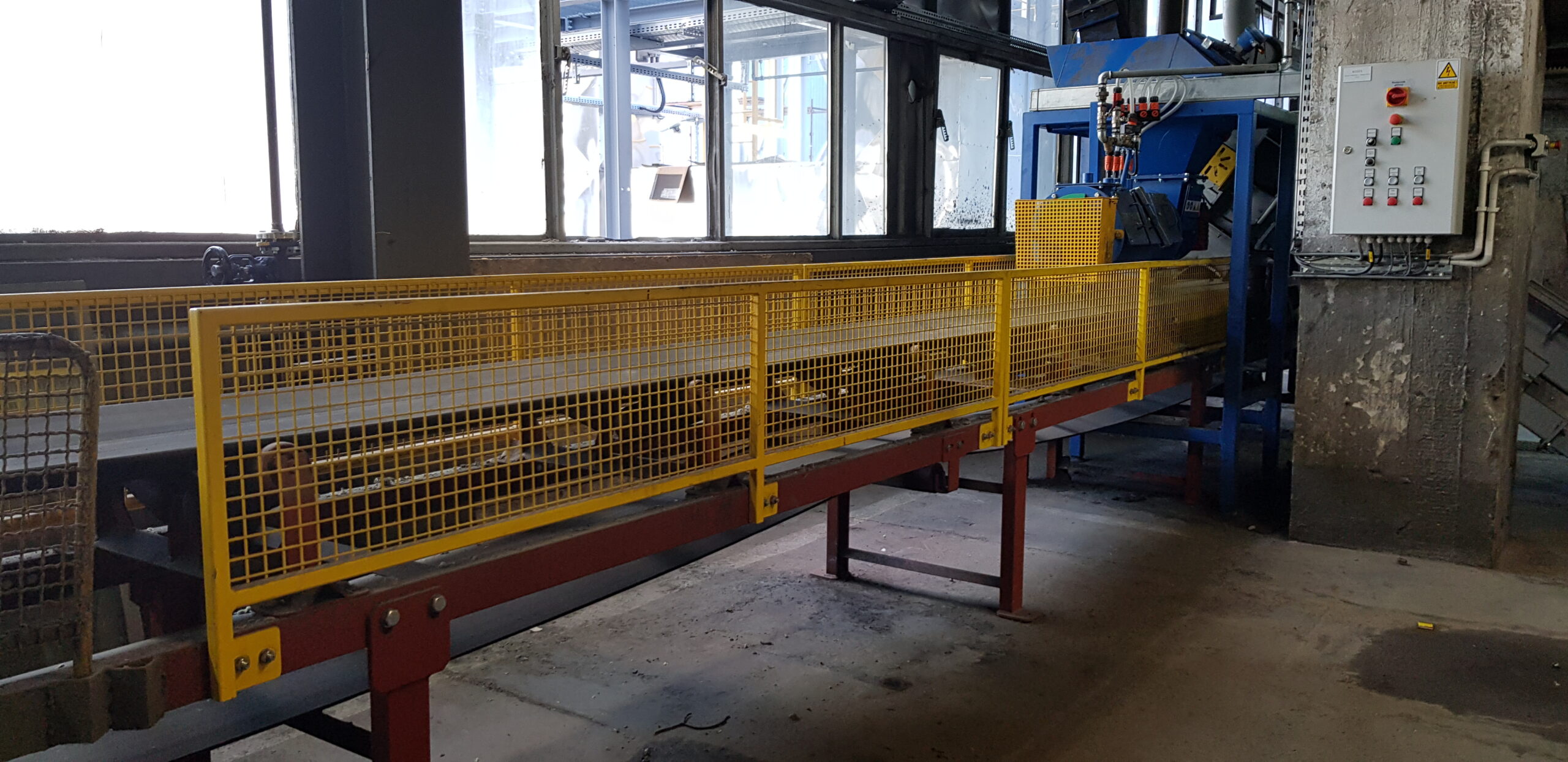
Belt conveyors are used as handling equipment to move the mining output resting on a belt, which is pulled along the path made from roller sets by a friction drum drive.

OPERATING PRINCIPLE:
The material to be transported is conveyed by an endless belt, supported by carrier rollers and guided along the route by centring rollers. The belt is set in motion by its friction coupling to the drive drum.
DESIGN:
- The drive – a drive station containing a motor, a clutch, a reducer, and a brake.
- The belt – a carrying and pulling component; it forms a closed system in the vertical plane. It is used to transport loose materials in mine workings, combustible minerals (e.g., coal), and non-combustible ones (e.g., copper ore, salts).
- Sets of upper (carrying) and lower rollers support the belt’s upper and lower branches. They are used to support the conveyor belt during mining output transport. The rollers are assembled in sets (flat, trough systems).
- The purpose of upper (support) belt rollers is to support the belt with the mining output placed on it. They are fitted with shock-absorbing (rubber) rings. They cushion the mining output falling onto the belt and protect the belt structure and bearings.
- The lower rollers’ main function is usually to support the belt. In addition, directional rollers are mounted at the edge of the belt and serve to guide it so that it does not run off the rollers.
- Drums- the belt passes through the drums along the conveyor route. Their purpose is to change the direction of its movement. The drums are classified according to their function:
- drive drum – it is connected to the conveyor drive unit and is set in a rigid frame. It transmits the torsional moment coming from the drive to the drum surface. The friction between the drive drum and the belt running surface causes it to move along the route;
- return drum – housed in a unique frame to which the belt pre-tensioning mechanism is connected. Return drums are used to return the belt just at the end of the conveyor;
- tensioning drum – this element is responsible for the proper tension of the belt (necessary to create friction in the drive drum);
- deflecting (directional) drum – this drum has the task of increasing the angle of the belt on the drive or tensioning drums.
- Cleaning devices – are intended to clean the belts of adhering mining output that has not been discharged at the end of the conveyor. These components are located in the return path of the belt. They ensure increased belt life and reduce operating costs. The cleaning devices include:
- scrapers – which are used to clean the belt of residual material. They protect the belt against negative phenomena, e.g., sticking of material to the drums and rollers, belt slippage, and mechanical damage. They have a slatted, plate or segmented structure. They are reinforced with inserts made of hard alloys (e.g., sintered carbides).
- Front scrapers – these scrapers clean the belt on the discharge drum. The cleaning edges are made of hard and durable materials (e.g., sintered carbides). The front scrapers are of modular structure, which improves their operational effectiveness (the belts are cleaned evenly across their entire width).
- brushes – are located near the return drums and are used for cleaning the belts of loose and brittle materials.
PERFORMANCE CHARACTERISTICS OF CONVEYORS:
- Delivery speed
- Capacity
- Transported material
- Cross-sectional area of the load pile on the belt
- Drive power
Biomass is an important renewable fuel in Poland’s commercial and industrial energy sector. For Poland, the projected share of RES in final power generation is 31% in 2030. A figure of 15.6% was achieved in 2021. The document outlining Poland’s power generation policy until 2030 assumes the development of RES, including biofuels. Biomass will be used in distributed generation (and cogeneration) using locally available raw materials with sustainable exploitation of forest and agricultural areas.

The transport of biomass to the boiler is linked to the combustion technique used.
When designing the boiler fuel supply equipment, the distance over which biomass with specific properties is to be transported at a given capacity is considered.
Permissible noise emissions
and concentrations of explosive atmospheres of released dust must also be taken into consideration.
When transporting loose biomass (sawdust, pellets, woodchips) over short distances, screw conveyors are used.
The feeder auger is driven by an electric motor using a high-ratio gearbox. It rotates in an enclosed duct with an inlet hole at one end and a biomass collection hole at the other. Fuel flow cut-off valves are often installed at both ends.
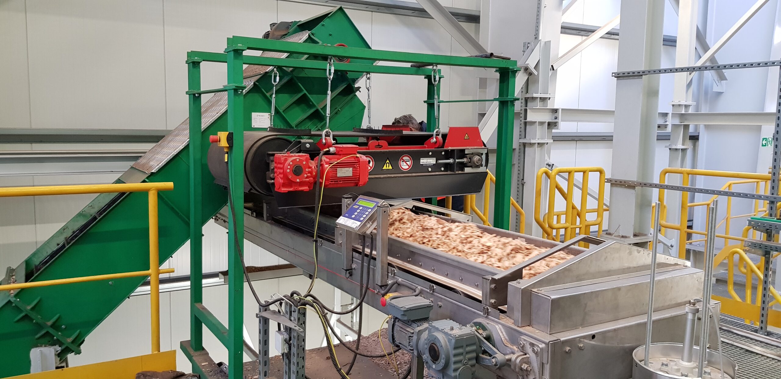
Belt conveyors are used if the distance between the boiler and the hopper is greater. Their simple design consists of a long belt mounted on pulleys, which can be additionally loaded. They are designed for fine biomass. Operational problems are related to angle restrictions, temperature changes and dust emissions deposited on the drive wheels.
Chain conveyors are installed to transport the fuel in different planes (up to 90 degrees). They are flexible in terms of the particle sizes conveyed, which can be freely distributed along the length of the chain. To avoid dust emissions, they are protected by barriers. These conveyors are relatively energy-intensive since they operate at low speeds, and therefore, also at low loads.
Biomass conveyor systems for transporting biomass to the boilers from the storage area are tailored to the individual needs of the customer – from the concept stage, through the system design, its manufacture, to its assembly and commissioning.

ECOSERV catalogue
We operate in the area of innovative technologies for environmental protection, such as pollutant neutralisation, dedusting, and filtration, dedicated to various branches of industry and power generation both in Poland and Europe. Our company is based on state-of-the-art and advanced solutions ensuring the reduction of pollutant emissions following European Union standards. We also have a wide range of equipment and installations for the heat engineering industry.


